Every industrial burner runs with more air than the chemistry requires. That surplus — excess air — exists for a reason, but it is paid for on every firing hour, and the only practical way to see it at the burner is the oxygen left in the flue gas.
This guide explains the relationship between flue gas O₂ and excess air, what each one costs when it is wrong in either direction, why a clean-looking O₂ reading can still be misleading, and how to set targets during commissioning that still hold three months later.
Short answer
Flue gas O₂ is a measurement; excess air is a calculation. Convert one to the other with the formula below so the number you quote to an operator means the same thing as the number in the commissioning report.
Set the target per fuel, per firing rate and per applicable emission limit — not one figure for the whole plant.
O₂ alone is not enough. CO is the constraint that tells you where the practical floor is. Tune to O₂ with CO in view, and leave a margin above the point where CO starts to climb.
Verify at low fire as well as high fire. A burner that is correct at maximum output can be starving or over-aerated at minimum output.
What excess air actually is
Stoichiometric combustion supplies exactly the oxygen needed to convert all fuel carbon to CO₂ and all fuel hydrogen to H₂O. Real burners cannot achieve perfect mixing in a finite combustion chamber, and real operating conditions move: fuel heating value varies, ambient air temperature and density change, linkages wear, and the air/fuel ratio control has a tolerance band.
Excess air is the engineering margin that keeps combustion complete despite all of that. It is normally expressed as a percentage of the stoichiometric air requirement, so 15% excess air means 1.15 times the theoretical air mass.
From flue gas O₂ to excess air
For dry flue gas and no significant CO, the relationship is:
with O₂ in percent by volume, dry basis.
| Measured dry O₂ | Approximate excess air |
|---|---|
| 1.0% | 5% |
| 2.0% | 11% |
| 3.0% | 17% |
| 4.0% | 24% |
| 5.0% | 31% |
| 6.0% | 40% |
| 8.0% | 62% |
| 10.0% | 92% |
Two practical notes. The curve steepens as O₂ falls, so near the bottom of the range a 0.5-point change in O₂ is a large change in excess air. And the formula is an approximation: it assumes dry measurement and negligible CO, and the exact relation shifts slightly with fuel composition. Your analyser will compute excess air from the same inputs — use its number, but understand where it comes from.
Why too much air costs money
Excess air adds nitrogen that takes no part in combustion. It is drawn in at ambient temperature, heated to the stack temperature and discharged. Every kilogram of it is fuel spent on nothing.
The first-order effect is proportionally simple: if the dry flue gas mass rises, the stack loss rises with it. Moving from 15% to 30% excess air means roughly 13% more dry flue gas mass passing through the same stack temperature difference — which is roughly 13% more of that loss component, not 13% of total fuel.
There are secondary costs as well:
Higher gas velocity and longer flame, which can affect heat transfer and, on some furnaces, flame impingement.
More NOx from the additional oxygen and nitrogen available in the flame zone, on burners not designed to compensate.
On oil and solid fuels, higher excess air can carry more particulate and increase deposition.
Why too little air is worse
Under-aerating crosses from inefficiency into safety and reliability territory:
CO rises steeply. As O₂ approaches the practical floor, carbon monoxide and unburned hydrocarbons increase faster than efficiency improves.
Soot and deposits. On liquid fuels, locally oxygen-starved zones produce soot, which then fouls the chamber and the convection surfaces.
Flame quality degrades. Long, lazy, luminous flames, pulsation and poor ignition stability usually follow.
Unburnt fuel in the chamber is an explosion hazard. Purge and safety interlocks exist precisely because this condition can occur; tuning must never be used to compensate for a mechanical fault.
Saving one efficiency point by running at the edge of the CO knee is a poor trade. The usual practice is to find the knee, then set the burner above it with a margin that covers control tolerance and normal fuel variation.
The reading can lie: air ingress
A probe in the stack measures what reaches the probe, not what happened in the flame. Air drawn in through a leaking door, expansion joint, flange or unsealed penetration raises measured O₂ without contributing any combustion air. The result is an apparently well-tuned burner that is, in fact, running rich.
Signals worth checking:
| Observation | What it can mean |
|---|---|
| O₂ rises as load falls, with no control change | Air ingress, or air/fuel ratio nonlinearity at low fire |
| O₂ higher at the outlet than upstream in the same duct | Leakage between the two points |
| CO₂ lower than expected for the fuel | Dilution by ingress air |
| CO present alongside high O₂ | Poor mixing or a local starved zone, not a global air shortage |
Test the duct before tuning it. A portable analyser traversed across a duct section and a check of the burner mounting flange and chamber access points will usually settle the question in an hour.
Targets by fuel and application
The table below gives typical commissioning starting points used in industrial practice. They are starting points, not a standard: the burner manufacturer's data, the applicable emission limit and the CO reading all take precedence.
| Fuel / application | Typical dry O₂ starting point | Notes |
|---|---|---|
| Natural gas, packaged boiler | About 3% (≈17% excess air) | Confirm against the low-NOx burner's own window; some designs need more air at the head |
| LPG | About 3% | Higher density affects injector and fan sizing rather than the target itself |
| Light oil / diesel | About 4–5% | Slightly higher margin helps against nozzle condition drift |
| Heavy oil | About 5–7% | Margin protects against viscosity and atomization variation |
| Biomass | Considerably higher | Fuel variability and grate/gasification air split dominate |
Two constraints override the table. First, an approved burner is approved within defined conditions — EN 676 covers the construction, operation and control of forced draught gas burners and includes requirements for the safety functions exercised during commissioning [1]. Second, local emission limits set the floor: within the EU, medium combustion plants from 1 MW to below 50 MW are subject to emission limit values for SO₂, NOx and dust, and NOx responds directly to excess air [5]. A target that ignores either is not a target, it is a habit.
The NOx trade-off
Reducing excess air usually lowers thermal NOx, because it lowers peak flame temperature and reduces the oxygen available to combine with nitrogen. That is one reason low-NOx burners are commissioned lean. But the relationship is not linear and not free: internal flue gas recirculation and air staging change the local stoichiometry, so a low-NOx burner's optimum O₂ window can be narrower than a conventional burner's, and its CO knee can arrive sooner.
The consequence for commissioning is straightforward: do not copy a target from a conventional burner onto a low-NOx unit, and do not assume that lower O₂ always means lower NOx on a staged design. Measure both.
Controls: cam, electronic cam, O₂ trim
| Control arrangement | What it does | When it is worth the cost |
|---|---|---|
| Mechanical cam / linkage | Fixed air/fuel position relationship across the firing range | Stable fuel quality, steady load, modest efficiency ambition |
| Electronic cam (servo) | Programmable position curve, easier to correct at intermediate points | Wide firing range, multi-fuel, frequent load changes |
| O₂ trim (closed loop) | Measures flue gas O₂ and trims the air actuator toward a setpoint | Load swings, fuel heating value variation, altitude or ambient variation, tight NOx compliance |
Trim is not a substitute for a correct baseline. It corrects drift around a setpoint; if the baseline curve is wrong, it will hold the burner at the wrong place precisely. It also needs a maintained analyser: an O₂ cell drifts and ages, and an uncalibrated sensor in a closed loop is worse than no loop at all.
A commissioning sequence you can record
Confirm the burner is mechanically sound: nozzle or gas head clean, linkages tight, fan and damper free, sensors in place. Tuning cannot fix a mechanical fault.
Warm the unit to normal operating temperature and hold a steady load for a period long enough for readings to stabilise — typically at least 15–30 minutes.
Insert the probe at a representative point, upstream of any dilution air, and check for ingress before trusting the numbers.
Start at high fire. Set air and fuel to the manufacturer's data, then trim toward the O₂ target while watching CO.
Step down through the firing range. Record O₂, CO, NOx, stack temperature, fuel pressure, air pressure and flame signal at each point.
Identify the CO knee, then set each point above it with an agreed margin.
Repeat the sweep upward. Hysteresis between the two directions is a finding, not an annoyance — record it.
Confirm ignition, flame stability and flame signal at minimum fire, and confirm the purge and safety sequence operates as designed.
Seal and mark adjusted linkages; record the final positions.
Re-test after any nozzle, gas orifice, fan or control change, and schedule periodic re-testing.
What to put in the commissioning record
| Item | Why it matters later |
|---|---|
| Fuel data | Heating value and composition, or oil certificate of analysis; the baseline for every future comparison |
| Firing rates tested | Results at intermediate points, not only maximum and minimum |
| O₂, CO, NOx, stack temperature per point | The evidence that the unit was set correctly |
| Ambient conditions | Air temperature and altitude change the available mass of air |
| Analyser make, model, calibration date | A reading without a calibration record proves nothing |
| Actuator and linkage positions | Needed to restore the setup after maintenance |
| Applicable emission limit | The constraint that justified the chosen target |
Analyser choice matters too. Portable electrochemical instruments are practical for tuning, and ASTM D6522 defines a test method for NOx, CO and O₂ from natural gas-fired boilers and process heaters using such analysers — while also warning that electrochemical cells have cross-sensitivities and should not be applied to other pollutants or sources without investigating interferences [2]. Regulatory measurements follow different methods; in the United States, for example, O₂ and CO₂ from stationary sources are determined instrumentally under Method 3A of 40 CFR Part 60 [3].
Common mistakes
Tuning at one firing rate. The most frequent cause of a burner that passes commissioning and then trips or smokes at 20% load.
Chasing O₂ without CO. Optimising a number that does not represent combustion completeness.
Ignoring air ingress. Reporting an efficiency gain that is actually dilution.
Using a nominal heating value. Gas heating value varies; ISO 6976 defines how to calculate calorific value, density and Wobbe index from composition, and your supplier's data is the input you should be using [4].
Changing the nozzle or gas orifice without re-tuning. Flow changes; the air curve does not follow automatically.
Setting the target to the emission limit exactly. No margin for fuel variation, and no room for the next service interval.
FAQ
What flue gas O₂ should a gas burner run at?Around 3% dry O₂ is a common starting point for packaged natural gas boilers, but the final figure depends on the burner design, the load point and the applicable NOx limit. Treat it as a starting point for commissioning, not a specification.
Does lower O₂ always mean better efficiency?Only until CO starts to rise. Below that point you are trading complete combustion for a smaller stack loss, and the trade usually loses.
Can I tune with a handheld analyser?Yes, for adjustment and for periodic checks, provided it is calibrated and you understand its measurement method and cross-sensitivity limits [2]. Formal compliance testing needs the method that applies in your jurisdiction.
Why does O₂ read higher at low fire?Air/fuel ratio curves are rarely perfectly linear, and leakage becomes a larger fraction of a smaller gas flow. Check both the curve and the duct.
Does an O₂ trim system remove the need for tuning?No. Trim corrects drift around a setpoint. The setpoint and the base curve still have to be right.
Discuss your combustion setup with BNTET
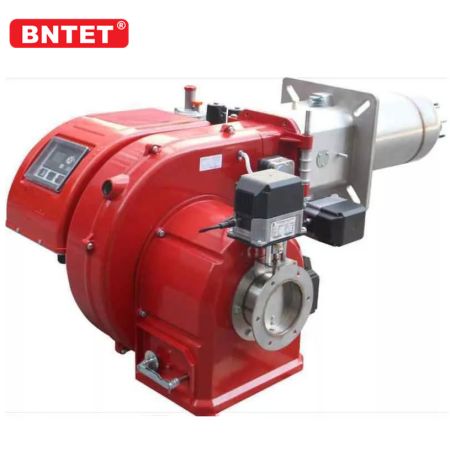
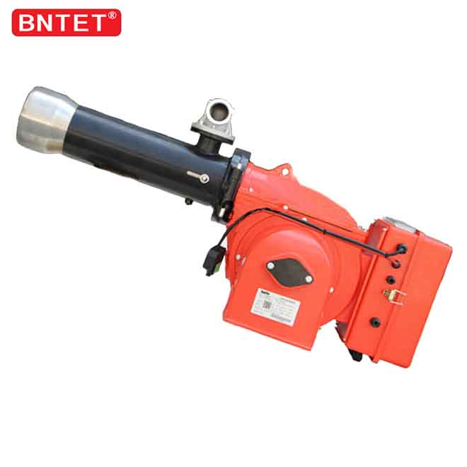
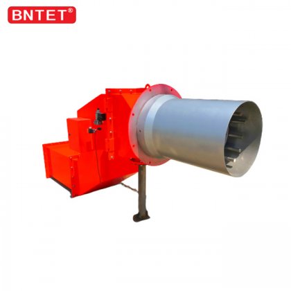
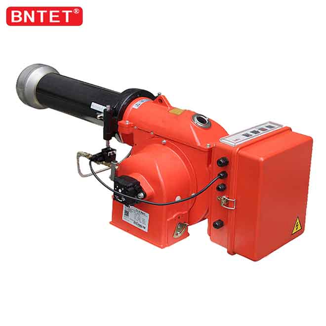
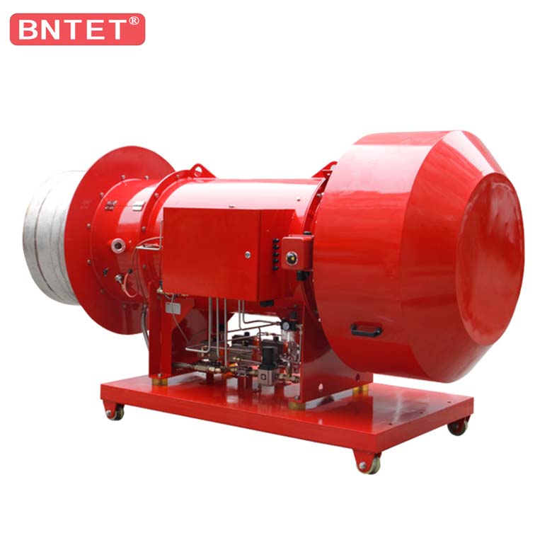
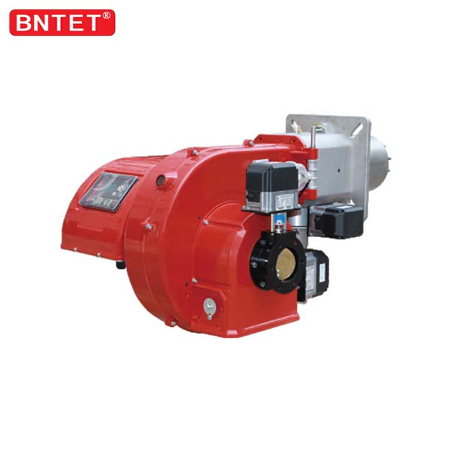
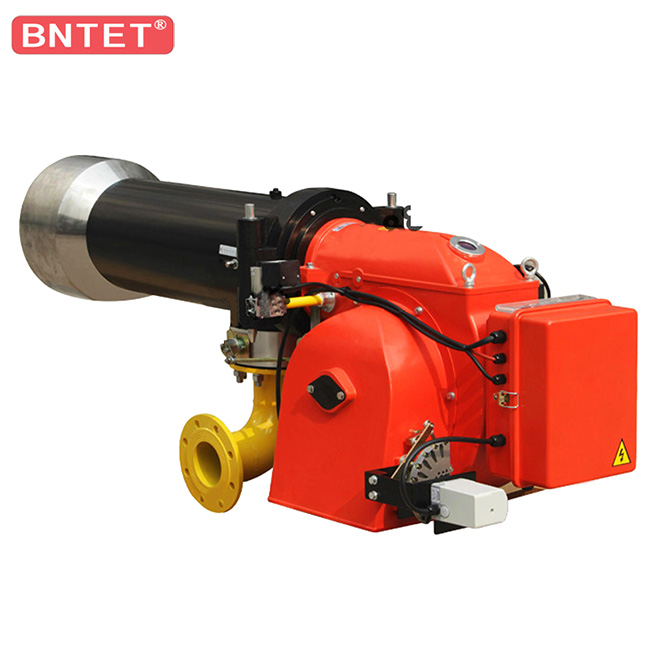
BNTET supplies industrial gas burners in single-stage, two-stage and modulating configurations, low NOx burners where emission limits drive the design, and dual fuel units where fuel availability varies. If your unit cycles rather than modulates, turndown ratio and minimum firing rate is the companion topic: a burner that cannot hold low load will not hold a stable O₂ reading either.
Send your fuel data, firing range and the emission limits that apply on site through the contact page and the team can discuss which control arrangement suits the duty.
Bring the CO reading with the O₂ reading — a target set without both is only half a measurement.
References
CEN. EVS-EN 676:2020/AC:2022, Forced draught burners for gaseous fuels. https://www.evs.ee/en/evs-en-676-2020-ac-2022
ASTM International. ASTM D6522-20: Standard Test Method for Determination of Nitrogen Oxides, Carbon Monoxide, and Oxygen Concentrations in Emissions from Natural Gas-Fired Reciprocating Engines, Combustion Turbines, Boilers, and Process Heaters Using Portable Analyzers. https://www.astm.org/d6522-20.html
U.S. Environmental Protection Agency. 40 CFR Part 60, Appendix A-3, Method 3A — Determination of Oxygen and Carbon Dioxide Concentrations in Emissions from Stationary Sources. https://www.ecfr.gov/current/title-40/chapter-I/subchapter-C/part-60/appendix-Appendix%20A-3%20to%20Part%2060
International Organization for Standardization. ISO 6976:2016, Natural gas — Calculation of calorific values, density, relative density and Wobbe indices from composition. (Standard designation; no public full-text link.)
European Parliament and Council. Directive (EU) 2015/2193 on the limitation of emissions of certain pollutants into the air from medium combustion plants. https://eur-lex.europa.eu/legal-content/EN/TXT/?uri=CELEX%3A32015L2193
ASME. ASME PTC 4-2013, Fired Steam Generators — Performance Test Codes. (Standard designation; referenced for formal efficiency testing rather than routine tuning.)