Abstract
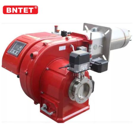
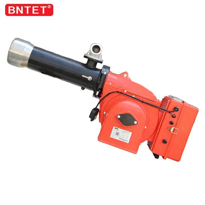
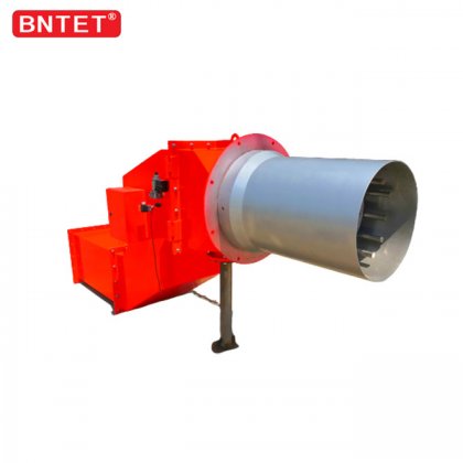
In heavy thermal processing sectors such as cement clinker manufacturing, lime calcination, rotary metallurgy, and hazardous waste incineration, process stability depends directly on the aerodynamic performance of rotary kiln burners[2, 5]. Unlike standard boiler fireboxes with enclosed geometries, a rotary kiln is an open-ended, rotating counter-current cylinder where the burner flame must sustain a defined clinkering or sintering thermal profile without impinging on interior refractory linings[1, 4]. Engineered by Bona Thermal Energy (BNTET), this engineering analysis evaluates the fluid mechanics of multi-channel flame shaping, momentum-to-heat ratio optimization, refractory wear protection, and multi-fuel co-firing capabilities[3, 6].
1. Multi-Channel Aerodynamic Architecture of Rotary Kiln Burners
To provide operators with independent control over flame length, divergent angle, and core temperature, high-performance rotary kiln burners divide combustion air into separate concentric channels[1, 7]:
                      Multi-Channel Kiln Burner Tip
                                    │
    ┌───────────────────────────────┼───────────────────────────────┐
    ▼                               ▼                               ▼
Outer Axial Air Channel       Swirl (Radial) Air Channel      Primary Fuel Delivery Core
(High-Velocity Jet: >180 m/s) (Helical Vanes: 120-160 m/s)    (Pulverized Coal / Gas / Liquid)
Shapes Flame Envelope &       Induces Internal Recirculation  Centerline Dual Fuel Injection
Controls Overall Length       Promotes Root Ignition Safety   With Inert Ceramic Shielding
Outer Axial Air Annulus: High-velocity air jets (typically discharged at velocities of 180 to 240 m/s) form an aerodynamic boundary envelope around the flame core. By adjusting the axial momentum flux, operators can lengthen the flame and project thermal radiation deep into the calcination zone without ballooning against kiln refractory bricks[3].
Radial / Swirl Air Channel: Internal helical vanes or tangentially angled nozzles impart angular momentum to the air stream. The resulting centrifugal forces create a stable Internal Recirculation Zone (IRZ) at the burner tip, continuously drawing hot, secondary kiln gases (often preheated to 800°C - 1000°C) into the root of the flame to accelerate fuel ignition[1, 4].
Core Multi-Fuel Delivery Passage: Liquid fuel lances, radial natural gas spuds, or pulverized fuel channels are nested within the central axis. The nozzle configuration ensures homogeneous blending while shielding the fuel delivery lines from back-radiated thermal shock[2].
2. Flame Momentum and Primary Air Ratio Optimization
Modern industrial kilns prioritize minimizing primary air consumption to maximize thermal recovery from high-temperature secondary clinker cooling air[2, 6]:
| Kiln Operating Metric | Legacy Single/Dual-Channel Burner | Modern Multi-Channel Burner (BNTET) |
| Primary Air Percentage | 15% – 25% of total combustion air | 6% – 10% (Substantially reduced cold air intake)[4] |
| Specific Flame Momentum ($G_m$) | 1,000 – 1,400 N/MW | 1,500 – 2,200 N/MW (Enhanced core rigidity)[1] |
| Secondary Air Entrainment | Low / Inefficient thermal blending | High (Accelerated induction of 900°C preheated air)[2] |
| Combustion Zone NOx Level | 1,200 – 1,600 mg/Nm³ | 600 – 900 mg/Nm³ (Staged aerothermal reduction)[6] |
| Turn-Down Flexibility | 1:2 to 1:3 | 1:4 to 1:6 (Adaptive to varied raw mix feeds) |
A higher specific momentum ($G_m$) paired with a lower primary air ratio ensures that the flame remains rigid, symmetrical, and resistant to buoyancy-induced upward deflection, protecting kiln roof refractories while cutting fuel consumption by 3% to 5%[1, 5].
3. High-Temperature Wear Protection and Material Specifications
Because rotary kiln burners are suspended inside kiln hoods exposed to high-velocity abrasive dust, radiant heat above 1,400°C, and sulfur/alkali gaseous attack, structural hardware must withstand severe conditions[3, 7]:
High-Nickel Alloy Outer Shells: Burner discharge nozzles and gas spuds are cast from high-heat and corrosion-resistant alloys (e.g., AISI 310S or Inconel 601), preventing oxidation, sagging, and thermal creep fatigue[7].
Corundum and Silicon Carbide Ceramic Linings: Pulverized fuel conveyance ducts are vulnerable to mechanical abrasion. Inner elbows and delivery channels are lined with monolithic castable silicon carbide (SiC) or sintered alumina ceramic rings, extending continuous operational service life beyond 36 months[3].
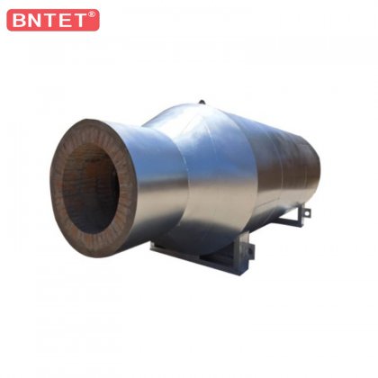
Protective Castable Refractory Anchors: The exterior body of the burner lance inside the kiln hood is wrapped with heavy-duty refractory anchors and coated with low-cement corundum refractory castables, insulating internal gas and oil conduits from the high thermal radiation environment[2].
4. Multi-Fuel Co-Firing and Alternative Fuel Utilization
To mitigate fuel cost spikes and achieve decarbonization objectives, industrial plants frequently co-fire secondary or alternative fuels[5]:
Simultaneous Multi-Fuel Capability: Burner controllers permit on-demand transitions and proportional blending between pulverized coal, natural gas, diesel, and heavy residual oil.
Alternative Solid Fuels (RDF / Biomass): Dedicated large-bore central passages allow the co-firing of refuse-derived fuels (RDF), ground plastics, or shredded biomass, helping operators substitute up to 40% to 60% of fossil fuel thermal inputs without destabilizing the kiln burning zone[5, 6].
Low-NOx In-Kiln Aerodynamics: By creating an oxygen-starved, reducing atmosphere immediately around the fuel discharge, fuel-bound nitrogen is transformed into inert molecular N2 before encountering high-temperature secondary air, keeping baseline NOx emissions within environmental compliance standards[4, 6].
5. Conclusion and Industrial Kiln Sourcing
Selecting the appropriate configuration of rotary kiln burners is essential for stabilizing clinker quality, extending refractory campaign life, and optimizing thermal efficiency[1, 3]. Bona Thermal Energy (BNTET) manufactures custom multi-channel kiln burners ranging from 5 MW to 120 MW, engineered to handle natural gas, coal dust, residual oils, and alternative fuel streams.
For bespoke kiln aerodynamic simulations, burner sizing calculations, and refractory upgrade consultations, please
References
Turns, S. R. (2012). An Introduction to Combustion: Concepts and Applications (3rd ed.). McGraw-Hill Education.
https://www.mheducation.com/highered/product/1259025946.html Baukal, C. E. (Ed.). (2013). The John Zink Hamworthy Combustion Handbook: Applications (2nd ed., Vol. 3). CRC Press / Taylor & Francis Group.
https://doi.org/10.1201/b15112 Lefebvre, A. H., & McDonell, V. G. (2017). Atomization and Sprays (2nd ed.). CRC Press / Taylor & Francis Group.
https://doi.org/10.1201/9781315120911 Warnatz, J., Maas, U., & Kohler, R. W. (2006). Combustion: Physical and Chemical Fundamentals, Modeling and Simulation, Experiments, Pollutant Formation (4th ed.). Springer-Verlag Berlin Heidelberg.
https://doi.org/10.1007/978-3-540-45363-5 Glassman, I., Yetter, R. A., & Glumac, N. G. (2014). Combustion (5th ed.). Academic Press / Elsevier.
https://doi.org/10.1016/C2011-0-05856-7 United States Environmental Protection Agency (US EPA). (2016). Alternative Control Techniques (ACT) Document — NOx Emissions from Cement Manufacturing. EPA-453/R-94-004, Office of Air Quality Planning and Standards.
https://www.epa.gov/stationary-sources-air-pollution Bayvel, L., & Orzechowski, Z. (1993). Liquid Atomization. Taylor & Francis / CRC Press.
https://doi.org/10.1201/9781482276947